
CHECKING THE SPEED SENSOR
1. Check:
• Speed sensor output voltage
If out of specification -> Replace.
1. Check:
• Speed sensor output voltage
If out of specification -> Replace.

|
Output voltage reading cycle
0.6 V to 4.8 V to 0.6 V to 4.8 V |
a. Connect the test harness-S pressure sensor (3P) "1" to the speed sensor and wire harness as shown.
b. Connect the pocket tester (DC 20 V) to the speed sensor coupler (wire harness side) as shown.
b. Connect the pocket tester (DC 20 V) to the speed sensor coupler (wire harness side) as shown.

|
Pocket tester
90890-03112 Analog pocket tester YU-03112-C Test harness S - pressure sensor (3P) 90890-03207 YU-03207 |
• Positive tester probe -> white/yellow (wire harness color)
• Negative tester probe -> black/blue (wire harness color)
• Negative tester probe -> black/blue (wire harness color)

c. Set the main switch to "ON".
d. Elevate the rear wheel and slowly rotate it.
e. Measure the voltage of white/yellow and black/blue. With each full rotation of the rear wheel,
the voltage reading should cycle from 0.6 V to 4.8 V to 0.6 V to 4.8 V.
d. Elevate the rear wheel and slowly rotate it.
e. Measure the voltage of white/yellow and black/blue. With each full rotation of the rear wheel,
the voltage reading should cycle from 0.6 V to 4.8 V to 0.6 V to 4.8 V.
CHECKING THE O2 SENSOR
< Need Write-Up >
< Need Write-Up >
CHECKING THE ENGINE TEMPERATURE SENSOR
1. Remove:
• Engine temperature sensor
1. Remove:
• Engine temperature sensor

• Handle the engine temperature sensor with special care.
• Never subject the engine temperature sensor to strong shocks. If the engine temperature sensor is
dropped, replace it.
2. Check:
• Engine temperature sensor resistance
If out of specification -> Replace.
• Never subject the engine temperature sensor to strong shocks. If the engine temperature sensor is
dropped, replace it.
2. Check:
• Engine temperature sensor resistance
If out of specification -> Replace.

|
Engine temperature sensor resistance
2.63-2.78 Kohms at 20 °C (68 °F) 210-221 ohms at 100 °C (212 °F) |
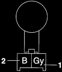
a. Connect the pocket tester (Ohms x 1 k) to the engine temperature sensor as shown.

|
Pocket tester
90890-03112 Analog pocket tester YU-03112-C |
• Tester positive probe -> black/blue "1"
• Negative tester probe -> brown "2"
• Negative tester probe -> brown "2"
b. Measure the engine temperature sensor resistance.
3. Install
• Engine temperature sensor
3. Install
• Engine temperature sensor
CHECKING THE INTAKE AIR PRESSURE SENSOR
1. Check:
• Intake air pressure sensor output voltage
If out of specification -> Replace.
1. Check:
• Intake air pressure sensor output voltage
If out of specification -> Replace.

|
Intake air pressure sensor output voltage
3.57-3.71 V |
a. Connect the test hamess-S pressure sensor (3P) "1" to the intake air pressure sensor and wire harness
as shown.
b. Connect the pocket tester (DC 20 V) to the intake air pressure sensor coupler as shown.
as shown.
b. Connect the pocket tester (DC 20 V) to the intake air pressure sensor coupler as shown.

|
Pocket tester
90890-03112 Analog pocket tester YU-03112-C Test harness S - pressure sensor 5S7 (3P) 90890-03211 YU-03211 |
• Positive tester probe -> pink (wire harness color)
• Negative tester probe -> black/blue (wire harness color)
• Negative tester probe -> black/blue (wire harness color)
c. Set the main switch to "ON".
d. Measure the intake air pressure sensor output voltage.
d. Measure the intake air pressure sensor output voltage.
CHECKING THE CRANKSHAFT POSITION SENSOR
1. Disconnect:
• Crankshaft position sensor coupler (from the wire harness)
2. Check:
• Crankshaft position sensor resistance
If out of specification -> Replace the crankshaft position sensor/stator assembly.
1. Disconnect:
• Crankshaft position sensor coupler (from the wire harness)
2. Check:
• Crankshaft position sensor resistance
If out of specification -> Replace the crankshaft position sensor/stator assembly.

|
Crankshaft position sensor resistance
248-372 Ohms |
a. Connect the pocket tester (Ohms x 100) to the crankshaft position sensor coupler as shown.

|
Pocket tester
90890-03112 Analog pocket tester YU-03112-C |
• Positive tester probe -> gray " 1 "
• Negative tester probe -> black "2"
• Negative tester probe -> black "2"
b. Measure the crankshaft position sensor resistance.
CHECKING THE LEAN ANGLE SENSOR
1. Remove:
• Lean angle sensor
2. Check:
• Lean angle sensor output voltage
If out of specification -> Replace.
1. Remove:
• Lean angle sensor
2. Check:
• Lean angle sensor output voltage
If out of specification -> Replace.

|
Lean angle sensor output voltage
Less than 45° 0.4-1.4 V More than 45° 3.7-4.4 V |
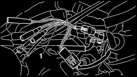
a. Connect the test harness-lean angle sensor (6P) "1" to the lean angle sensor and wire harness as shown.
b. Connect the pocket tester (DC 20 V) to the test harness-lean angle sensor (6P).
b. Connect the pocket tester (DC 20 V) to the test harness-lean angle sensor (6P).

|
Pocket tester
90890-03112 Analog pocket tester YU-03112-C Test harness - lean angle sensor (6P) 90890-03209 YU-03209 |
• Positive tester probe -> yellow/green (wire harness color)
• Negative tester probe -> black/blue (wire harness color)
• Negative tester probe -> black/blue (wire harness color)
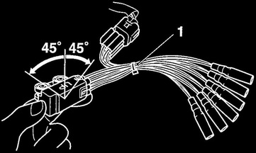
c. Turn the main switch to "ON".
d. Turn the lean angle sensor to 45°.
e. Measure the lean angle sensor output voltage.
d. Turn the lean angle sensor to 45°.
e. Measure the lean angle sensor output voltage.
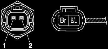
CHECKING THE THROTTLE POSITION SENSOR
1. Remove:
• Throttle position sensor (from the throttle body)
2. Check:
• Throttle position sensor maximum resistance
If out of specification -> Replace the throttle position sensor.
1. Remove:
• Throttle position sensor (from the throttle body)
2. Check:
• Throttle position sensor maximum resistance
If out of specification -> Replace the throttle position sensor.

|
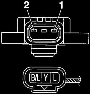
Resistance
3.08-5.72 Kohms (L-B/L) |
a. Connect the pocket tester (Ohms. x 1 k) to the throttle position sensor terminals as shown.

|
Pocket tester
90890-03112 Analog pocket tester YU-03112-C |
• Positive tester probe -> blue"1"
• Negative tester probe -> black/blue "2"
• Negative tester probe -> black/blue "2"
b. Measure the throttle position sensor maximum resistance.
3. Install:
• Throttle position sensor
3. Install:
• Throttle position sensor

When installing the throttle position sensor, adjust its angle properly.
CHECKING THE INTAKE AIR TEMPERATURE SENSOR
1. Remove:
• Intake air temperature sensor
1. Remove:
• Intake air temperature sensor

• Handle the intake air temperature sensor with special care.
• Never subject the intake air temperature sensor to strong shocks. If the intake air temperature sensor is
dropped, replace it.
2. Check:
• Intake air temperature sensor resistance
If out of specification -> Replace.
• Never subject the intake air temperature sensor to strong shocks. If the intake air temperature sensor is
dropped, replace it.
2. Check:
• Intake air temperature sensor resistance
If out of specification -> Replace.

|
Intake air temperature sensor resistance
5.4-6.6 Kohms at 0 °C (32 °F) 290-390 ohms at 80 °C (176 °F) |
a. Connect the pocket tester (Ohms x 100) to the intake air temperature sensor terminal as shown.

|
Pocket tester
90890-03112 Analog pocket tester YU-03112-C |
b. Immerse the intake air temperature sensor "1" in a container filled with water "2".

Make sure that the intake air temperature sensor terminals do not get wet.
c. Place a thermometer "3" in the water.
c. Place a thermometer "3" in the water.
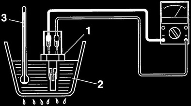
d. Slowly heat the water, and then let it cool down to the specified temperature.
e. Measure the intake air temperature sensor resistance.
e. Measure the intake air temperature sensor resistance.
© 2013-15 cvvmax. No animals, HDs or Ducatis were harmed in the making of this site.