
|
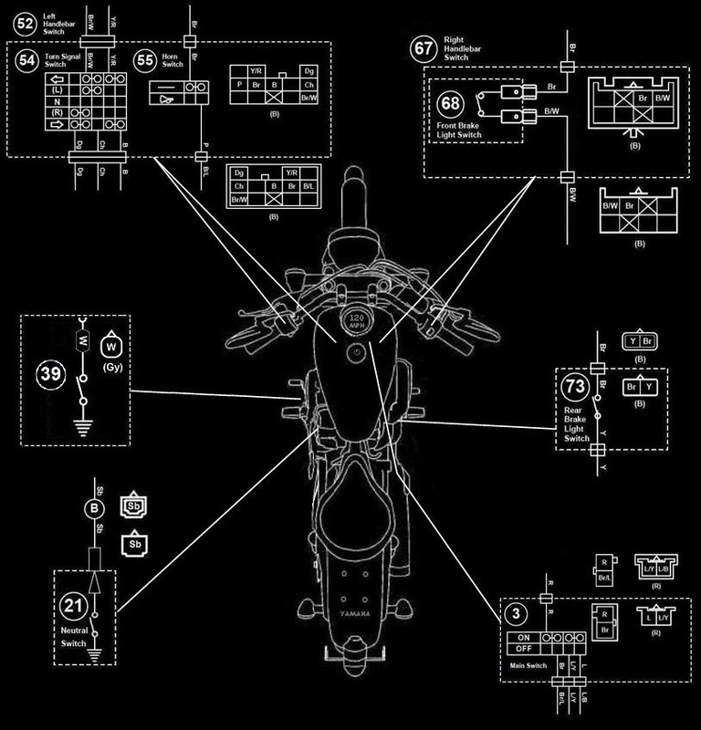
3. Main switch
21. Neutral switch 39. Oil Level Switch 54. Turn signal switch |
55. Horn switch
68. Front brake light switch 73. Rear brake light switch |
CHECKING SWITCHES
Check each switch for continuity with the pocket tester. If the continuity reading is incorrect, check the wiring connections and if necessary, replace the switch.
Check each switch for continuity with the pocket tester. If the continuity reading is incorrect, check the wiring connections and if necessary, replace the switch.

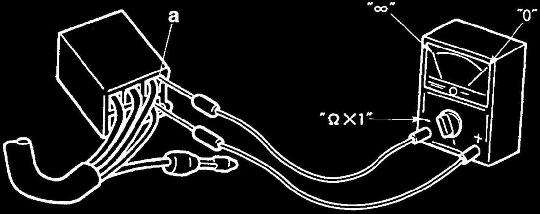
Never insert the tester probes into the coupler terminal slots "a". Always insert the probes from the opposite end of the coupler, taking care not to loosen or damage the leads.

|
Pocket tester
90890-03112 Analog pocket tester YU-03112-C |

• Before checking for continuity, set the pocket tester to "0" and to the "ohms x 1" range.
• When checking for continuity, switch back and forth between the switch positions a
few times.
• When checking for continuity, switch back and forth between the switch positions a
few times.
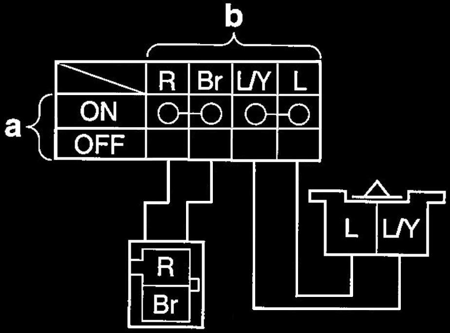
The switches and their terminal connections are illustrated as in the following example of the main switch.
The switch positions "a" are shown in the far left column and the switch lead colors "b" are shown in the top row.
The continuity (i. e., a closed circuit) between switch terminals at a given switch position is indicated by "O—O"-
There is continuity between the red and brown leads, and between the blue/yellow and blue leads when the switch is set to "ON".
CHECKING THE OIL LEVEL SWITCH
1. Drain:
• Engine oil
2. Remove:
• Oil level switch (from the crankcase)
3. Check:
• Oil level switch resistance
If out of specification -> Replace the oil level switch. Oil level switch
1. Drain:
• Engine oil
2. Remove:
• Oil level switch (from the crankcase)
3. Check:
• Oil level switch resistance
If out of specification -> Replace the oil level switch. Oil level switch

|
Maximum level position resistance
484-536 ohms Minimum level position resistance 114-126 ohms |
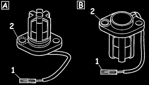
a. Connect the pocket tester (ohms x 100) to the oil level switch terminal as shown.

|
Pocket tester
90890-03112 Analog pocket tester YU-03112-C |
Minimum level position "A"
• Positive tester probe -> connector (white) "1"
• Negative tester probe -» body ground "2"
Maximum level position "B"
• Positive tester probe -> connector (white) "1"
• Negative tester probe -> body ground "2"
• Positive tester probe -> connector (white) "1"
• Negative tester probe -» body ground "2"
Maximum level position "B"
• Positive tester probe -> connector (white) "1"
• Negative tester probe -> body ground "2"
b. Measure the oil level switch resistance.
© 2013-15 cvvmax. No animals, HDs or Ducatis were harmed in the making of this site.