

ADJUSTING VALVE CLEARANCE
© cvvmax December 2013
The following procedure applies to all of the valves.
© cvvmax December 2013
The following procedure applies to all of the valves.

• Valve clearance adjustment should be made on a cold engine, at room temperature.
• When the valve clearance is to be measured or adjusted, the piston must be at top
dead center (TDC) on the compression stroke.
1. Remove:
• Fuel tank
• Front cylinder left cover
• Front cylinder right cover
• Rear cylinder left cover
• Rear cylinder right cover
2. Disconnect:
• Throttle position sensor coupler
• Fuel hose (fuel filter to inlet pipe assembly)
3. Remove:
• Fuel filter
• Rear cylinder head guard
• Rear cylinder left cover bracket
4. Disconnect:
• Crankcase breather hose
5. Remove:
• Hose holder
6. Disconnect:
• Spark plug caps
7. Remove:
• Spark plugs
8. Remove:
• Damper cover
• Generator cover damper
• Timing mark accessing screw
• Crankshaft end accessing screw
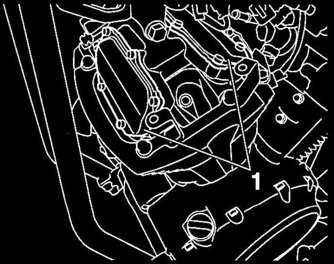
9. Remove:
• Front cylinder tappet covers " 1 "
• When the valve clearance is to be measured or adjusted, the piston must be at top
dead center (TDC) on the compression stroke.
1. Remove:
• Fuel tank
• Front cylinder left cover
• Front cylinder right cover
• Rear cylinder left cover
• Rear cylinder right cover
2. Disconnect:
• Throttle position sensor coupler
• Fuel hose (fuel filter to inlet pipe assembly)
3. Remove:
• Fuel filter
• Rear cylinder head guard
• Rear cylinder left cover bracket
4. Disconnect:
• Crankcase breather hose
5. Remove:
• Hose holder
6. Disconnect:
• Spark plug caps
7. Remove:
• Spark plugs
8. Remove:
• Damper cover
• Generator cover damper
• Timing mark accessing screw
• Crankshaft end accessing screw
9. Remove:
• Front cylinder tappet covers " 1 "
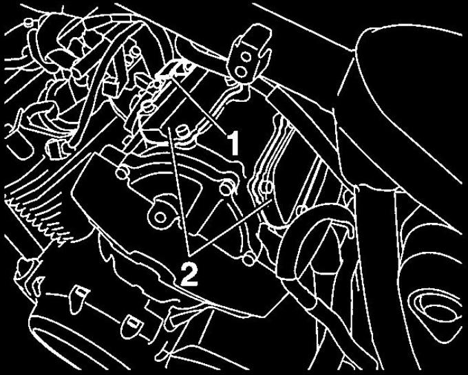
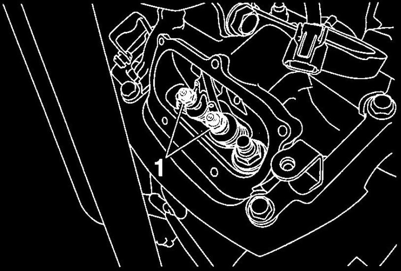
10. Remove:
• Fuel filter bracket " 1 "
• Rear cylinder tappet covers "2"
• Fuel filter bracket " 1 "
• Rear cylinder tappet covers "2"
11. Measure:
• Valve clearance
If Out of specification -> Adjust.
• Valve clearance
If Out of specification -> Adjust.

Valve clearance (cold)
Intake
0.08-0.12 mm (0.0031-0.0047 in)
Exhaust
0.22-0.26 mm (0.0087-0.0102 in)
Front cylinder
a. Turn the crankshaft counterclockwise.
Intake
0.08-0.12 mm (0.0031-0.0047 in)
Exhaust
0.22-0.26 mm (0.0087-0.0102 in)
Front cylinder
a. Turn the crankshaft counterclockwise.
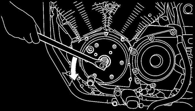
b. When the front cylinder piston is at TDC on the compression stroke, align the TDC
mark "a" on the generator rotor with the slot "b" in the generator cover.
mark "a" on the generator rotor with the slot "b" in the generator cover.

• When the piston is at TDC on the compression stroke, there should be clearance
between the valve stem tips and their respective rocker arm adjusting screws.
• If there is no clearance, rotate the crankshaft counterclockwise one turn.
between the valve stem tips and their respective rocker arm adjusting screws.
• If there is no clearance, rotate the crankshaft counterclockwise one turn.

c. Measure the valve clearance with a thickness gauge.

Thickness gauge
90890-03180
Feeler gauge set
YU-26900-9
Rear cylinder
a. Turn the crankshaft counterclockwise from the front cylinder piston TDC by
300 degrees.
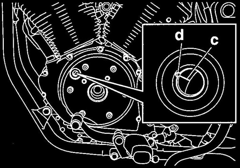
b. When the rear cylinder piston is at TDC on the compression stroke, align the TDC
mark "c" on the generator rotor with the slot "d" in the generator cover.
90890-03180
Feeler gauge set
YU-26900-9
Rear cylinder
a. Turn the crankshaft counterclockwise from the front cylinder piston TDC by
300 degrees.
b. When the rear cylinder piston is at TDC on the compression stroke, align the TDC
mark "c" on the generator rotor with the slot "d" in the generator cover.

• When the piston is at TDC on the compression stroke, there should be clearance
between the valve stem tips and their respective rocker arm adjusting screws.
• If there is no clearance, rotate the crankshaft counterclockwise one turn.
between the valve stem tips and their respective rocker arm adjusting screws.
• If there is no clearance, rotate the crankshaft counterclockwise one turn.
c. Measure the valve clearance with a thickness gauge.

Thickness gauge
90890-03180
Feeler gauge set
YU-26900-9
12. Adjust:
• Valve clearance
a. Loosen the locknuts "1".
90890-03180
Feeler gauge set
YU-26900-9
12. Adjust:
• Valve clearance
a. Loosen the locknuts "1".
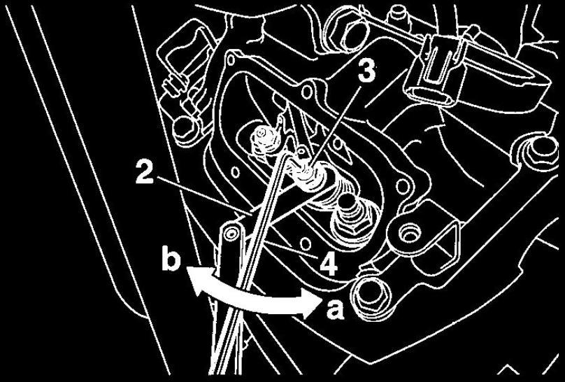
b. Insert a thickness gauge "2" between the end of the adjusting screw "3" and the
valve tip.
valve tip.

Thickness gauge
90890-03180
Feeler gauge set
YU-26900-9
c. Turn the adjusting screw in direction "a" or "b" with the hexagon wrench "4"
until the specified valve clearance is obtained.
Direction "a"
Valve clearance is increased.
Direction "b"
Valve clearance is decreased.
90890-03180
Feeler gauge set
YU-26900-9
c. Turn the adjusting screw in direction "a" or "b" with the hexagon wrench "4"
until the specified valve clearance is obtained.
Direction "a"
Valve clearance is increased.
Direction "b"
Valve clearance is decreased.
d. Hold the adjusting screw to prevent it from moving and tighten the locknut to
specification.
specification.

Locknut (rocker arm adjusting screw)
27 Nm (2.7 m-kgf, 20 ft-lbf)
e. Measure the valve clearance again.
f. If the valve clearance is still out of specification, repeat all of the valve
clearance adjustment steps until the specified clearance is obtained.
13. lnstall:
• Rear cylinder tappet covers
• Fuel filter bracket
• Front cylinder tappet covers

Rear cylinder tappet cover bolt
10 Nm (1.0 m-kgf, 7.2 ft-lbf)
Front cylinder tappet cover bolt
10 Nm (1.0 m-kgf, 7.2 ft-lbf)
14. Install:
• Crankshaft end accessing screw (along with a NEW O-Ring)
• Timing mark accessing screw (along with a NEW O-Ring)
• Generator cover damper
• Damper cover
10 Nm (1.0 m-kgf, 7.2 ft-lbf)
Front cylinder tappet cover bolt
10 Nm (1.0 m-kgf, 7.2 ft-lbf)
14. Install:
• Crankshaft end accessing screw (along with a NEW O-Ring)
• Timing mark accessing screw (along with a NEW O-Ring)
• Generator cover damper
• Damper cover

Damper cover bolt
7 Nm (0.7 m-kgf, 5.1 ft-lbf)
15.lnstall:
• All removed parts
7 Nm (0.7 m-kgf, 5.1 ft-lbf)
15.lnstall:
• All removed parts

For installation, reverse the removal procedure.

© 2013-15 cvvmax. No animals, HDs or Ducatis were harmed in the making of this site.