


|


|


|
Diagrams available for Download;
For USA/Canada Models ONLY;
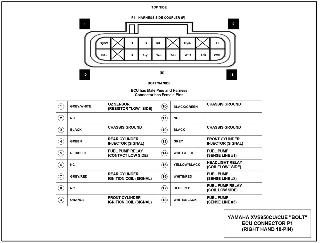
1 • ECU 18 Pin Connector (P1) - Pin Out Diagram - v1.0
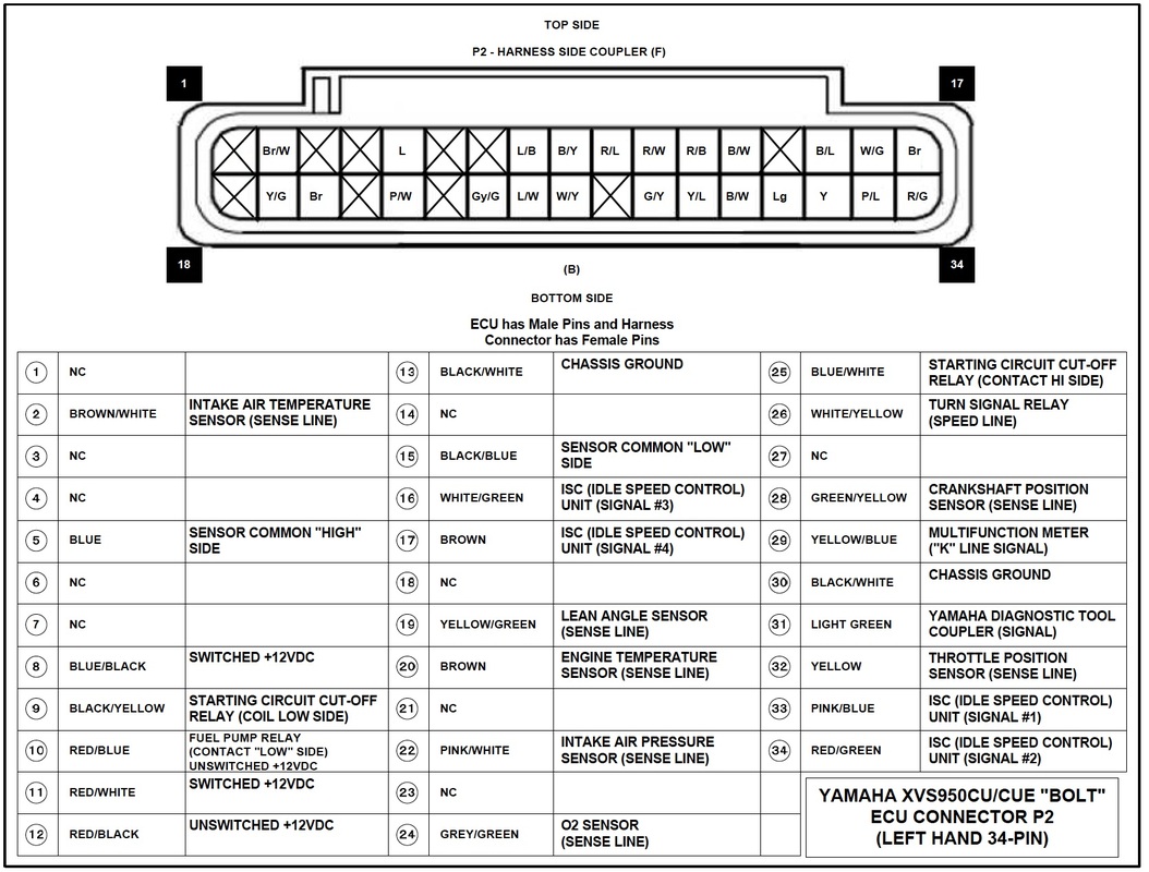
2 • ECU 34 Pin Connector (P2) - Pin Out Diagram - v1.0
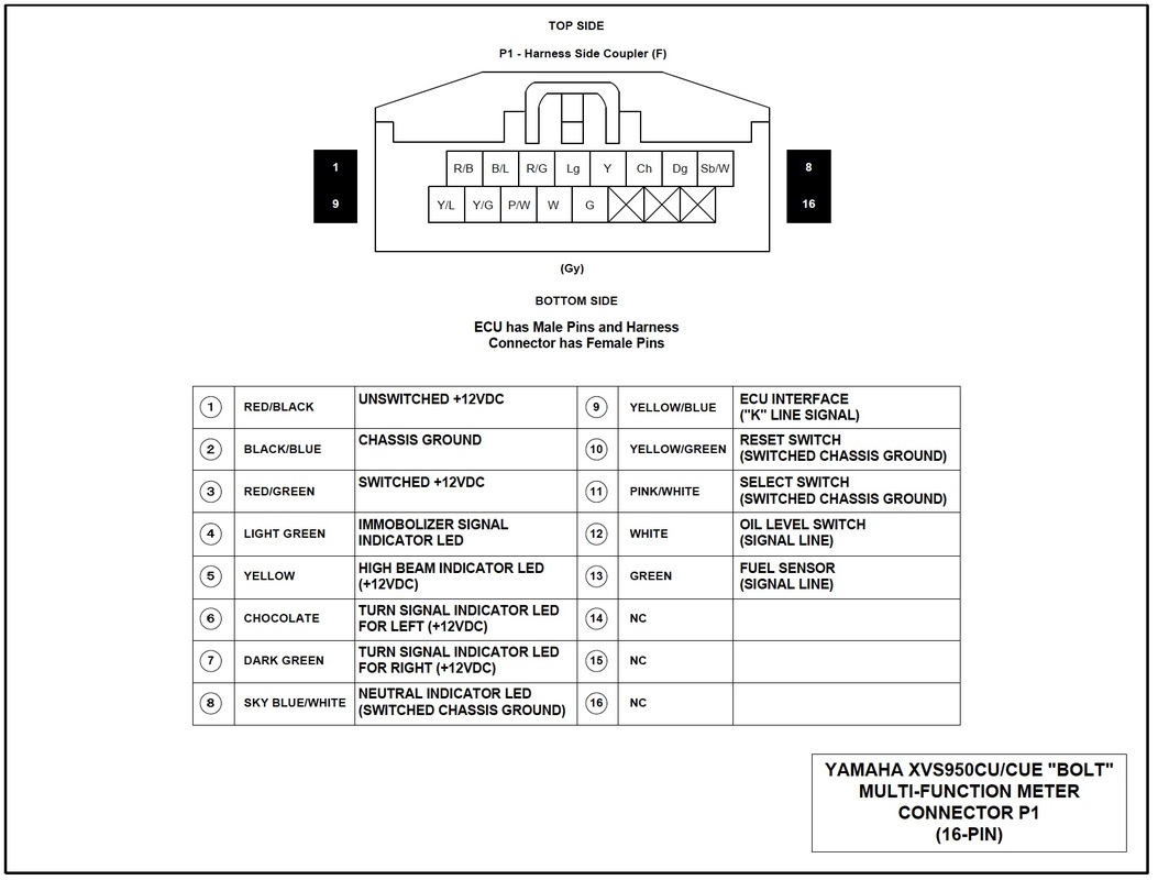
3 • Multi-Function Meter 16 Pin Connector (P1) - Pin Out Diagram - v1.0
4 • Main Wiring Diagram (B/W with B/W Labels) - v1.3
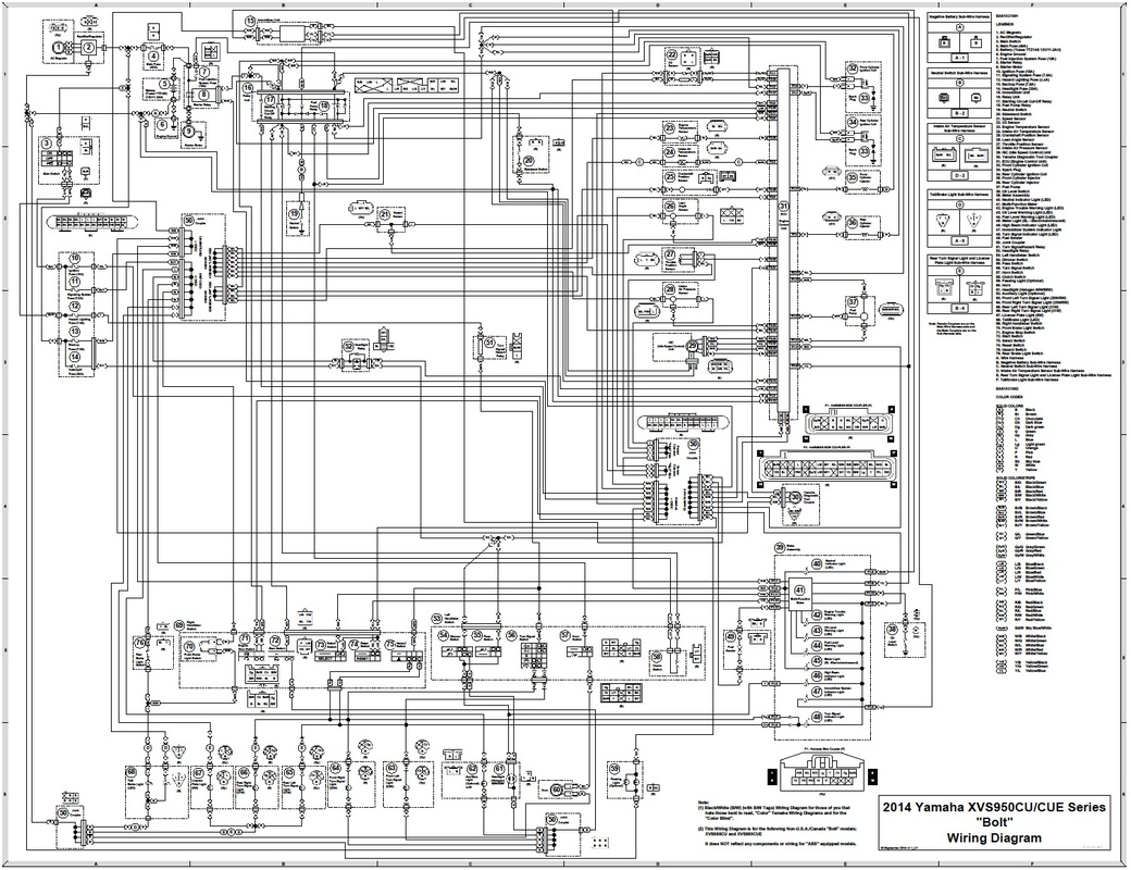
5 • Main Wiring Diagram (B/W with B/W Tags) - v1.3
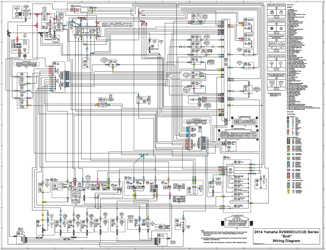
6 • Main Wiring Diagram (B/W with Colored Tags) - v1.3
7 • Main Wiring Diagram w/Several Mod Devices (B/W with Colored Tags) - v1.3
8 • Rear Turn Signal Running Lights Wiring Diagram - Option-1/Relays
(B/W with Colored Tags) - v1.0
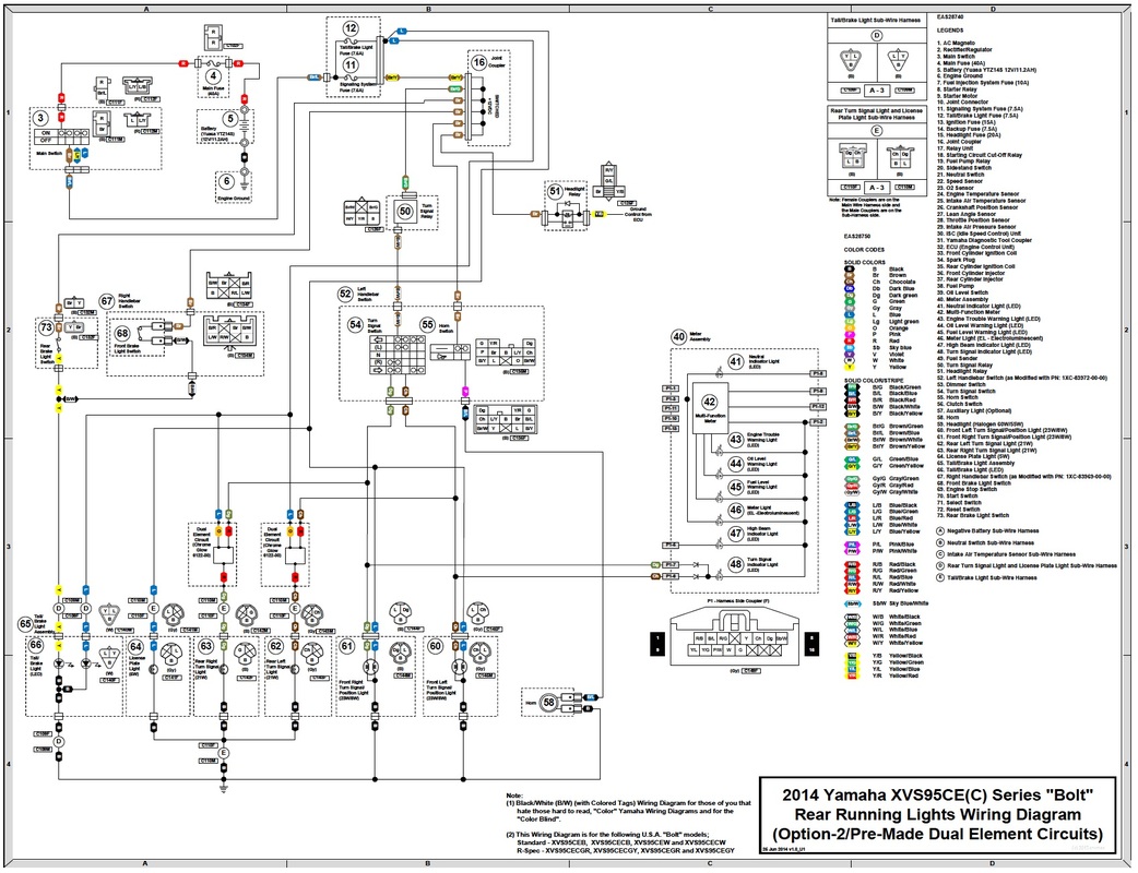
9 • Rear Turn Signal Running Lights Wiring Diagram - Option-2/Pre-Made Dual Element Circuit
(B/W with Colored Tags) - v1.0
10 • Rear Turn Signal Running Lights Wiring Diagram - Option-3/D.I.Y. Dual Element Circuit
(B/W with Colored Tags) - v1.0
For Other than the USA/Canada Models;
11 • ECU 18 Pin Connector (P1) - Pin Out Diagram - v1.0
12 • ECU 34 Pin Connector (P2) - Pin Out Diagram - v1.0
13 • Multi-Function Meter 16 Pin Connector (P1) - Pin Out Diagram - v1.0
14 • Main Wiring Diagram (B/W with B/W Tags) - v1.1
15 • Main Wiring Diagram (B/W with Colored Tags) - v1.1
For ALL Models;
16 • Battery Tender and USB Port Wiring Diagram - v1.0
17 • Auxilary Light Coupler and Cigarette Lighter Socket and USB Port Wiring Diagram - v1.0
18 • Power Commander V Installation Wiring Diagram - v1.0
19 • Power Commander V with AutoTune (w/No O2 Controller) Installation Wiring Diagram - v1.0
20 • Power Commander V with AutoTune and O2 Controller Installation Wiring Diagram - v1.0
Scroll down to find the document desired...
For USA/Canada Models ONLY;
1 • ECU 18 Pin Connector (P1) - Pin Out Diagram - v1.0
2 • ECU 34 Pin Connector (P2) - Pin Out Diagram - v1.0
3 • Multi-Function Meter 16 Pin Connector (P1) - Pin Out Diagram - v1.0
4 • Main Wiring Diagram (B/W with B/W Labels) - v1.3
5 • Main Wiring Diagram (B/W with B/W Tags) - v1.3
6 • Main Wiring Diagram (B/W with Colored Tags) - v1.3
7 • Main Wiring Diagram w/Several Mod Devices (B/W with Colored Tags) - v1.3
8 • Rear Turn Signal Running Lights Wiring Diagram - Option-1/Relays
(B/W with Colored Tags) - v1.0
9 • Rear Turn Signal Running Lights Wiring Diagram - Option-2/Pre-Made Dual Element Circuit
(B/W with Colored Tags) - v1.0
10 • Rear Turn Signal Running Lights Wiring Diagram - Option-3/D.I.Y. Dual Element Circuit
(B/W with Colored Tags) - v1.0
For Other than the USA/Canada Models;
11 • ECU 18 Pin Connector (P1) - Pin Out Diagram - v1.0
12 • ECU 34 Pin Connector (P2) - Pin Out Diagram - v1.0
13 • Multi-Function Meter 16 Pin Connector (P1) - Pin Out Diagram - v1.0
14 • Main Wiring Diagram (B/W with B/W Tags) - v1.1
15 • Main Wiring Diagram (B/W with Colored Tags) - v1.1
For ALL Models;
16 • Battery Tender and USB Port Wiring Diagram - v1.0
17 • Auxilary Light Coupler and Cigarette Lighter Socket and USB Port Wiring Diagram - v1.0
18 • Power Commander V Installation Wiring Diagram - v1.0
19 • Power Commander V with AutoTune (w/No O2 Controller) Installation Wiring Diagram - v1.0
20 • Power Commander V with AutoTune and O2 Controller Installation Wiring Diagram - v1.0
Scroll down to find the document desired...
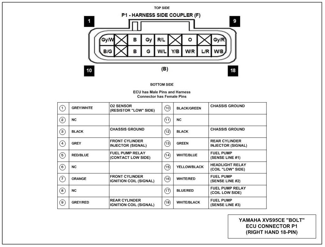
1 • ECU 18 Pin Connector (P1)
Pin Out Diagram © cvvmax December 2013 |
For USA/Canada Models ONLY

|
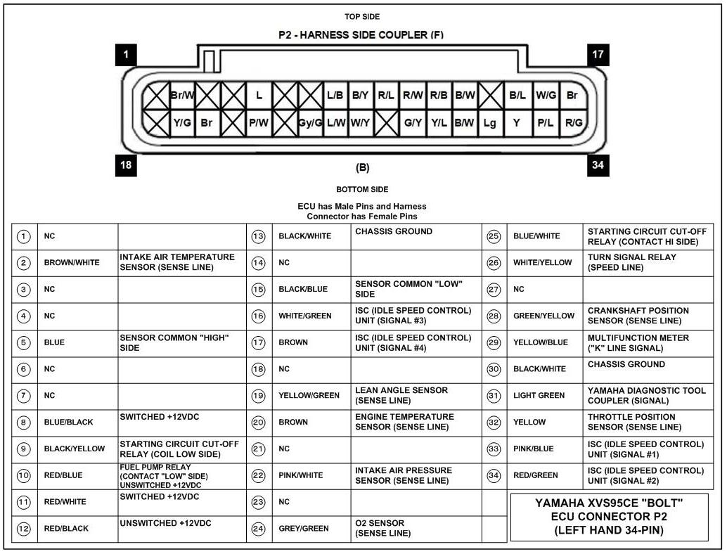
2 • ECU 34 Pin Connector (P2)
Pin Out Diagram © cvvmax December 2013 |
For USA/Canada Models ONLY

|
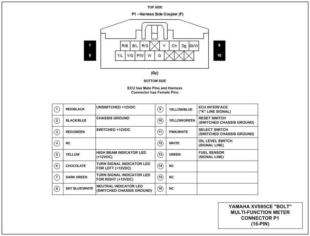
3 • Multi-Function Meter 16 Pin Connector (P1)
Pin Out Diagram © cvvmax December 2013 |
For USA/Canada Models ONLY

|
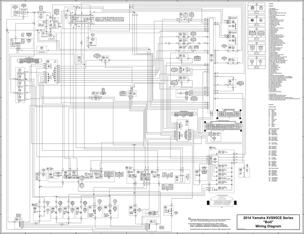
4 • Main Wiring Diagram
(B/W with B/W Labels - v1.3) © cvvmax December 2013 |
For USA/Canada Models ONLY
11" x 17" Size 
34" x 44" Eng "E" Size 
|
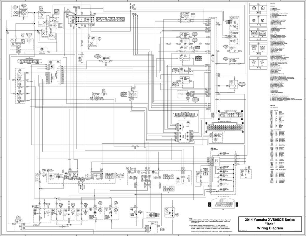
5 • Main Wiring Diagram
(B/W with B/W Tags - v1.3) © cvvmax December 2013 |
For USA/Canada Models ONLY
11" x 17" Size 
34" x 44" Eng "E" Size 
|
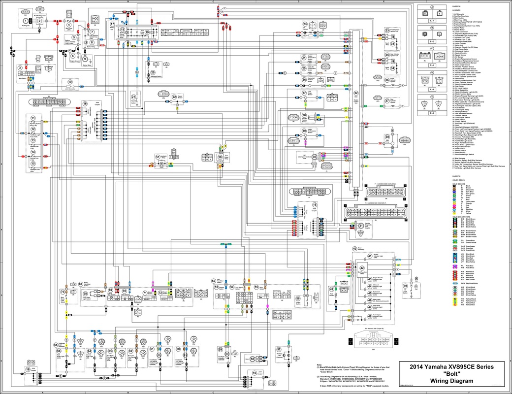
6 • Main Wiring Diagram
(B/W with Colored Tags - v1.3) © cvvmax December 2013 |
For USA/Canada Models ONLY
11" x 17" Size 
34" x 44" Eng "E" Size 
|
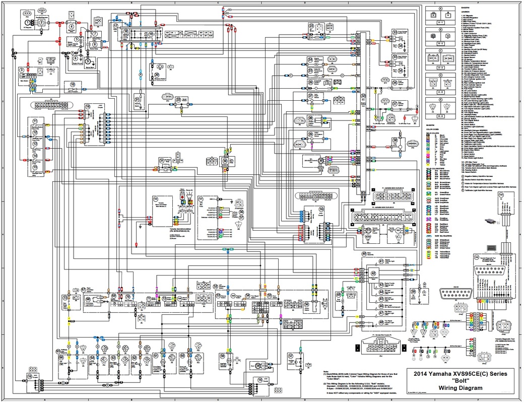
7 • Main Wiring Diagram w/Several Mod Devices
(B/W with Colored Tags - v1.3) © cvvmax December 2013 |
For USA/Canada Models ONLY
11" x 17" Size 
34" x 44" Eng "E" Size 
|
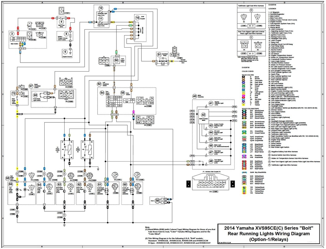
8 • Rear Turn Signal Running Lights Wiring Diagram
Option-1/Relays (B/W with Colored Tags) - v1.0 © cvvmax June 2014 |
For USA/Canada Models ONLY

|
9 • Rear Turn Signal Running Lights Wiring Diagram
Option-2/Pre-Made Dual Element Circuit (B/W with Colored Tags) - v1.0 © cvvmax June 2014 |
For USA/Canada Models ONLY

|
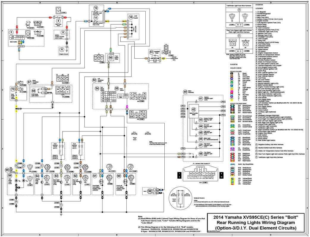
10 • Rear Turn Signal Running Lights Wiring Diagram
Option-3/D.I.Y. Dual Element Circuit (B/W with Colored Tags) - v1.0 © cvvmax June 2014 |
For USA/Canada Models ONLY

|
11 • ECU 18 Pin Connector (P1)
Pin Out Diagram © cvvmax May 2014 |
For Other than the USA/Canada Models

|
12 • ECU 34 Pin Connector (P2)
Pin Out Diagram © cvvmax May 2014 |
For Other than the USA/Canada Models

|
13 • Multi-Function Meter 16 Pin Connector (P1)
Pin Out Diagram © cvvmax May 2014 |
For Other than the USA/Canada Models

|
14 • Main Wiring Diagram
(B/W with B/W Tags - v1.0) © cvvmax May 2014 |
For Other than the USA/Canada Models
11" x 17" Size 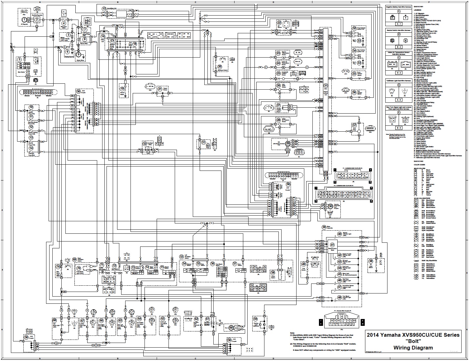
34" x 44" Eng "E" Size 
|
15 • Main Wiring Diagram w/Several Mod Devices
(B/W with Colored Tags - v1.0) © cvvmax May 2014 |
For Other than the USA/Canada Models
11" x 17" Size 
34" x 44" Eng "E" Size 
|
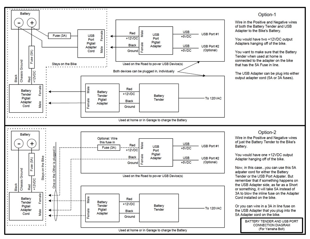
16 • Battery Tender and USB Port Wiring Diagram (v1.0)
© cvvmax April 2014 |
For ALL Models

|
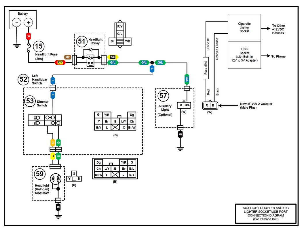
17 • Auxiliary Light Coupler and Cigarette Lighter Socket
and USB Port Wiring Diagram (v1.0) © cvvmax April 2014 |
For ALL Models

|
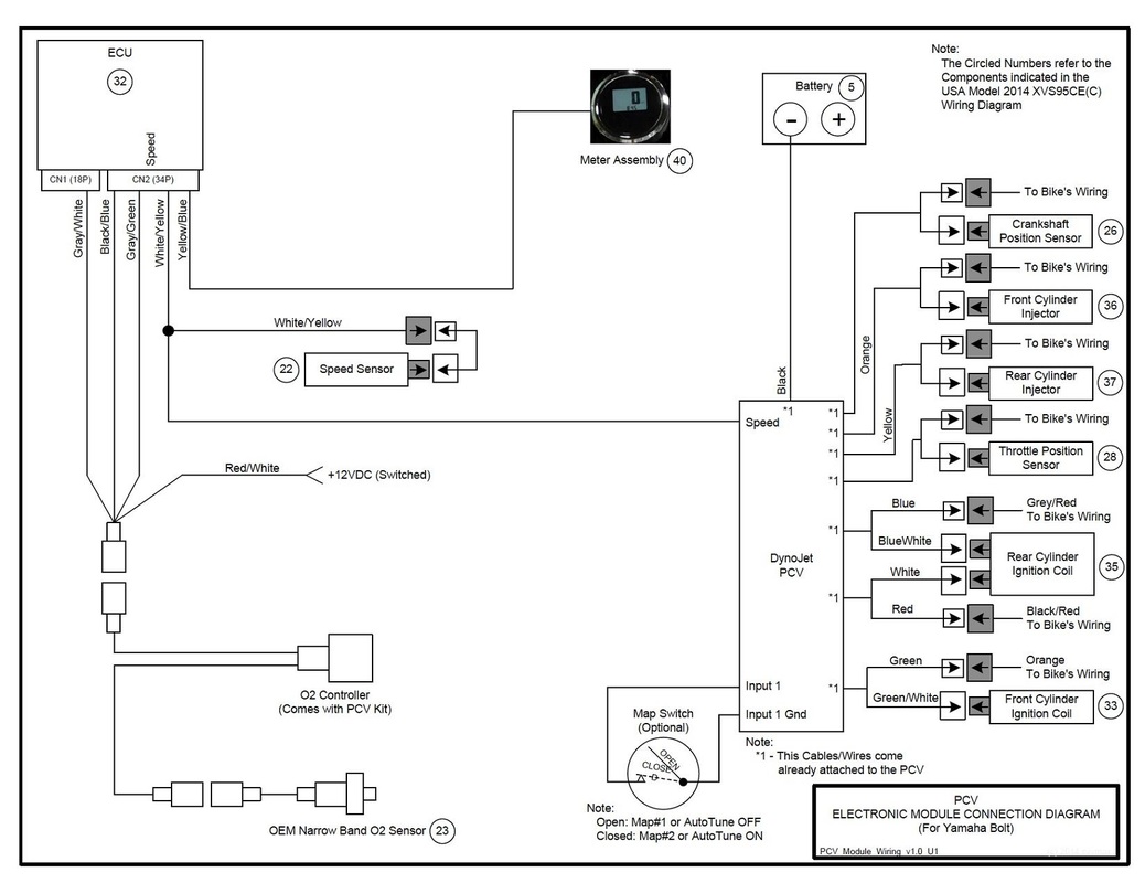
18 • Power Commander V Installation Wiring Diagram (v1.0)
© cvvmax April 2014 |
For ALL Models

|
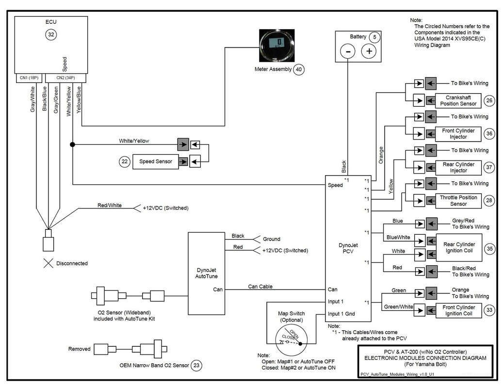
19 • Power Commander V with AutoTune (w/No O2 Controller)
Installation Wiring Diagram (v1.0) © cvvmax April 2014 |
For ALL Models

|
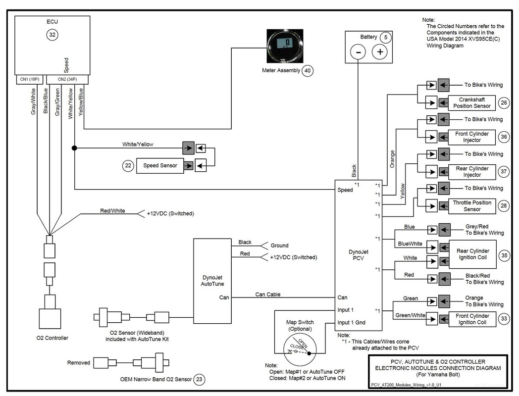
20 • Power Commander V with AutoTune and O2 Controller
Installation Wiring Diagram (v1.0) © cvvmax April 2014 |
For ALL Models

|
© 2013-15 cvvmax. No animals, HDs or Ducatis were harmed in the making of this site.