
CHECKING RELAYS
Check each relay for continuity with the pocket tester. If the continuity reading is incorrect, replace the relay.
Check each relay for continuity with the pocket tester. If the continuity reading is incorrect, replace the relay.

|
Pocket tester
90890-03112 Analog pocket tester YU-03112-C |
1. Disconnect the relay from the wire harness.
2. Connect the pocket tester (Ohms. x 1) and battery (+12VDC) to the relay terminal as shown.
Check the relay operation.
If out of specification -> Replace.
2. Connect the pocket tester (Ohms. x 1) and battery (+12VDC) to the relay terminal as shown.
Check the relay operation.
If out of specification -> Replace.
CHECKING THE RELAY UNIT (DIODE)
Relay unit (diode)
1. Check:
• Relay unit (diode)
If out of specification -> Replace.
Relay unit (diode)
1. Check:
• Relay unit (diode)
If out of specification -> Replace.

|
Pocket tester
90890-03112 Analog pocket tester YU-03112-C |

|
The pocket tester or the analog pocket tester readings are shown in the following table.
|
|
Continuity
Positive tester probe -> sky blue "1" Negative tester probe -> black/yellow "2" No continuity Positive tester probe -> black/yellow "2" Negative tester probe -> sky blue"1" Continuity Positive tester probe -> sky blue Negative tester probe -> blue/yellow "3" No continuity Positive tester probe -> blue/yellow "3" Negative tester probe -> sky blue"1" Continuity Positive tester probe -> sky blue Negative tester probe ->sky blue/white "4" No continuity Positive tester probe -> sky blue/white "4" Negative tester probe -> sky blue"1" Continuity Positive tester probe -> blue/green "5" Negative tester probe -> blue/yellow "3" No continuity Positive tester probe -> blue/yellow "3" Negative tester probe -> blue/green "5" |
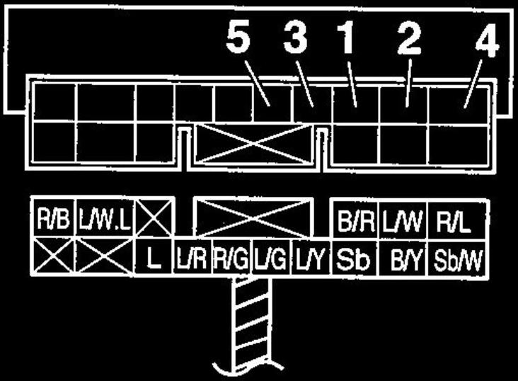
a. Disconnect the relay unit from the wire harness.
b. Connect the pocket tester (ohm x 1) to the relay unit terminals as shown.
c. Check the relay unit (diode) for continuity.
d. Check the relay unit (diode) for no continuity.
b. Connect the pocket tester (ohm x 1) to the relay unit terminals as shown.
c. Check the relay unit (diode) for continuity.
d. Check the relay unit (diode) for no continuity.
© 2013-15 cvvmax. No animals, HDs or Ducatis were harmed in the making of this site.