|
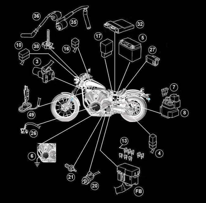
3. Main Switch
4. Main Fuse (40A) 5. Battery 6. Engine Ground 7. Fuel Injection System Fuse (10A) (Contained in 8 - Starter Relay Assembly) 10. Joint Coupler 13. Ignition Fuse (15A) (Inside of FB - Fuse Box) 16. Joint Coupler 17. Relay Unit (contains 19 - Fuel Pump Relay and 18 - Starting Circuit Cut-Off Relay) 20. Sidestand Switch |
21. Neutral Switch
26. Crankshaft Position Sensor 27. Lean Angle Sensor 32. ECU (Engine Control Unit) 33. Front Cylinder Ignition Coil 34. Spark Plug 35. Rear Cylinder Ignition Coil 38. Fuel Pump 67. Right Handlebar Switch 69. Engine Stop Switch FB. Fuse Box A. Negative Battery Sub-Wire Harness B. Neutral Switch Sub-Wire Harness |
|
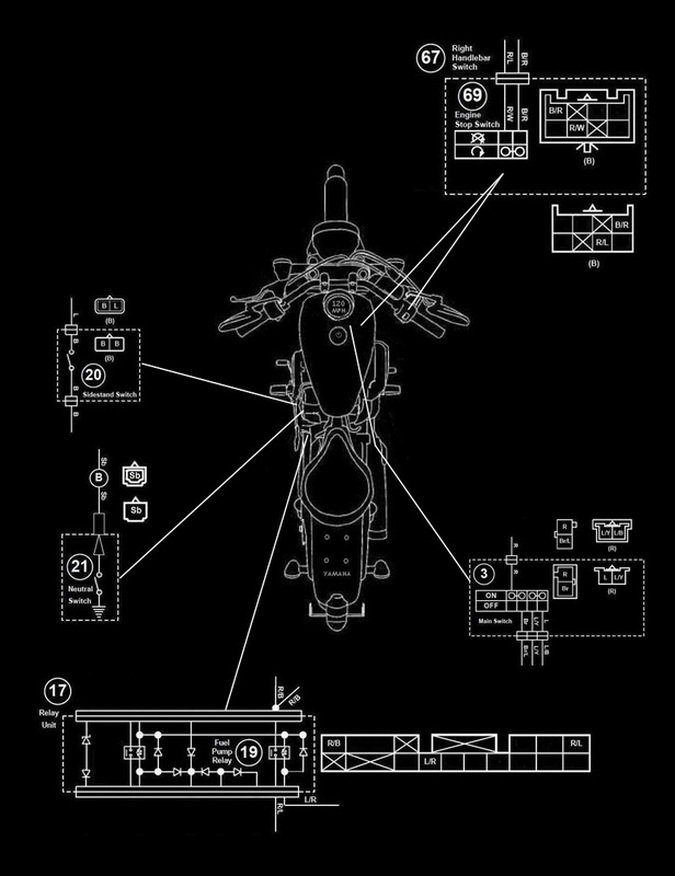
3. Main Switch
17. Relay Unit 19. Fuel Pump Relay 20. Sidestand Switch |
21. Neutral Switch
67. Right Handlebar Switch 69. Engine Stop Switch |
|
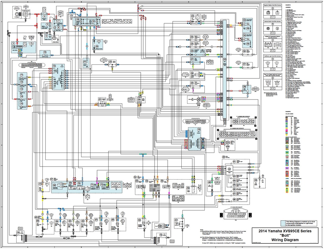
3. Main Switch
4. Main Fuse (40A) 5. Battery 6. Engine Ground 7. Fuel Injection System Fuse (10A) (Contained in 8 - Starter Relay Assembly) 10. Joint Coupler 13. Ignition Fuse (15A) (Inside of FB - Fuse Box) 16. Joint Coupler 17. Relay Unit (contains 19 - Fuel Pump Relay and 18 - Starting Circuit Cut-Off Relay) 20. Sidestand Switch |
21. Neutral Switch
26. Crankshaft Position Sensor 27. Lean Angle Sensor 32. ECU (Engine Control Unit) 33. Front Cylinder Ignition Coil 34. Spark Plug 35. Rear Cylinder Ignition Coil 38. Fuel Pump 67. Right Handlebar Switch 69. Engine Stop Switch FB. Fuse Box A. Negative Battery Sub-Wire Harness B. Neutral Switch Sub-Wire Harness |
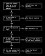
< Symptom >
The Ignition System fails to operate (No Spark or Intermittent Spark).
The Ignition System fails to operate (No Spark or Intermittent Spark).
Before Troubleshooting, remove the following part(s).
1. Left Side Cover
2. Rider Seat
3. Fuel Tank
4. Rear Cylinder Right Cover
5. Air Duct
1. Left Side Cover
2. Rider Seat
3. Fuel Tank
4. Rear Cylinder Right Cover
5. Air Duct
|

|

|

|

|

|
|

|
|

|

|

|
|

|

|

|
|

|

|

|
|

|

|

|
|

|

|

|
|

|

|

|
|

|

|

|
|

|

|

|
|

|

|

|
|

|

|

|
|

|

|

|
|

|

|

|

|

© 2013-15 cvvmax. No animals, HDs or Ducatis were harmed in the making of this site.