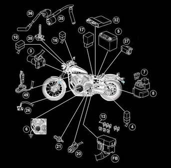
Click on the button to the right, to go to the Electric Starting System Troubleshooting Page. |
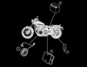
The Electric Starting System consists of the following;
Component No. Description 3 Main Switch 4 Main Fuse (40A) 5 Battery 6 Engine Ground 8 Starter Relay 9 Starter Motor 13 Ignition Fuse 16 Joint Coupler 17 Relay Unit 18 Starting Circuit Cut-Off Relay 20 Sidestand Switch 21 Neutral Switch 56 Clutch Switch 67 Right Handlebar Switch 69 Engine Stop Switch 70 Start Switch A Negative Battery Sub-Wire Harness B Neutral Switch Sub-Wire Harness |
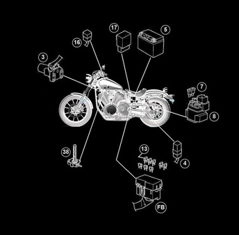
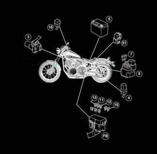
Click on the button to the right, to go to the
Fuel Pump System Troubleshooting Page. |
The Fuel Pump System consists of the following;
Component No. Description 3 Main Switch 4 Main Fuse (40A) 5 Battery 7 Fuel Injection System Fuse 13 Ignition Fuse 16 Joint Coupler 17 Relay Unit 19 Fuel Pump Relay 32 ECU (Engine Control Unit) 38 Fuel Pump 67 Right Handlebar Switch 69 Engine Stop Switch A Negative Battery Sub-Wire Harness |
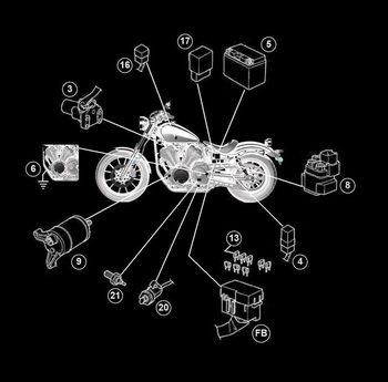
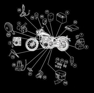
Click on the button to the right, to go to the Ignition System Troubleshooting Page. |
The Ignition System consists of the following;
Component No. Description 3 Main Switch 4 Main Fuse (40A) 5 Battery 6 Engine Ground 7 Fuel Injection System Fuse 10 Joint Coupler 13 Ignition Fuse 16 Joint Coupler 17 Relay Unit 19 Fuel Pump Relay 20 Sidestand Switch 21 Neutral Switch 26 Crankshaft Position Sensor 27 Lean Angle Sensor 32 ECU (Engine Control Unit) 33 Front Cylinder Ignition Coil 34 Spark Plug 35 Rear Cylinder Ignition Coil 38 Fuel Pump 67 Right Handlebar Switch 69 Engine Stop Switch A Negative Battery Sub-Wire Harness B Neutral Switch Sub-Wire Harness |
Click on the button to the right, to go to the Lighting System Troubleshooting Page. |
The Lighting System consists of the following;
Component No. Description 3 Main Switch 4 Main Fuse (40A) 5 Battery 7 Fuel Injection System Fuse 11 Signaling System Fuse 12 Tail/Brake Light Fuse 13 Ignition Fuse 15 Headlight Fuse 16 Joint Coupler 32 ECU (Engine Control Unit) 40 Meter Assembly 42 Multi-Function Meter 46 Meter Light 47 High Beam Indicator Light 51 Headlight Relay 52 Left Handlebar Switch 53 Dimmer Switch 57 Auxiliary Light (Optional) 59 Headlight 60 Front Left Turn Signal/Position Light 61 Front Right Turn Signal/Position Light 64 License Plate Light 65 Tail/Brake Light Assembly 66 Tail/Brake Light A Negative Battery Sub-Wire Harness D Tail/Brake Light Sub-Wire Harness E Rear Turn Signal Light and License Plate Light Sub-Wire Harness |
Click on the button to the right, to go to the Signaling System Troubleshooting Page. |
The Signaling System consists of the following;
Component No. Description 3 Main Switch 4 Main Fuse (40A) 5 Battery 6 Engine Ground 7 Fuel Injection System Fuse 11 Signaling System Fuse 13 Ignition Fuse 14 Backup Fuse 16 Joint Coupler 17 Relay Unit 21 Neutral Switch 22 Speed Sensor 32 ECU (Engine Control Unit) 39 0il Level Switch 40 Meter Assembly 41 Neutral Indicator Light 42 Multi-Function Meter 44 Oil Level Warning Light 45 Fuel Level Warning Light 48 Turn Signal Indicator Light 49 Fuel Sender 50 Turn Signal Relay 52 Left Handlebar Switch 54 Turn Signal Switch 55 Horn Switch 58 Horn 60 Front Left Turn Signal/Position Light 61 Front Right Turn Signal/Position Light 62 Rear Left Turn Signal Light 63 Rear Right Turn Signal Light 65 Tail/Brake Light Assembly 66 Tail/Brake Light 68 Front Brake Light Switch 73 Rear Brake Light Switch A Negative Battery Sub-Wire Harness B Neutral Switch Sub-Wire Harness D Tail/Brake Light Sub-Wire Harness E Rear Turn Signal Light and License Plate Light Sub-Wire Harness |
|
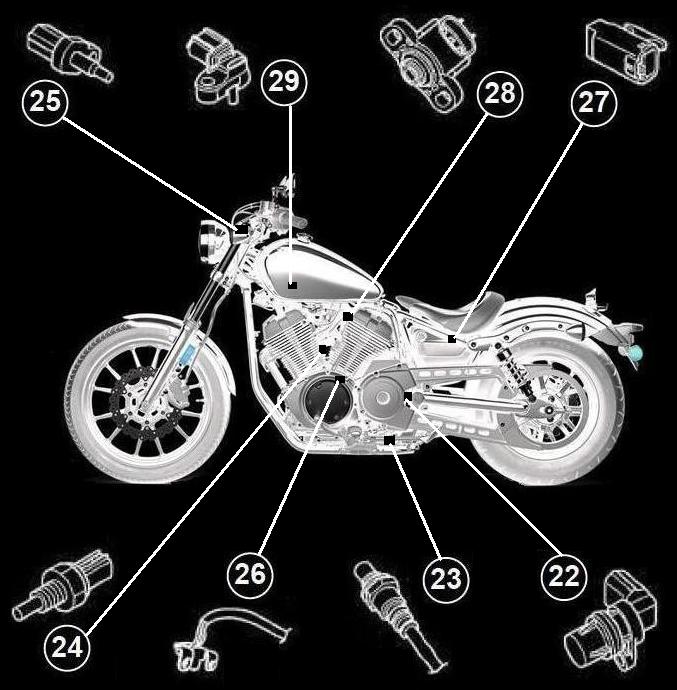
Although some Sensors are checked within some of the above Sub-Systems, many Sensors are not included and so, this section lists all of the Sensors on the bike, including all of them in thise Sub-Systems above.
Component No. Description 22 Speed Sensor 23 O2 Sensor 24 Engine Temperature Sensor 25 Intake Air Temperature Sensor 26 Crankshaft Position Sensor 27 Lean Angle Sensor 28 Throttle Position Sensor 29 Intake Air Pressure Sensor |
|
Other Components not covered in any category above;
Component No. Description xx Fuel Injector |

© 2013-15 cvvmax. No animals, HDs or Ducatis were harmed in the making of this site.